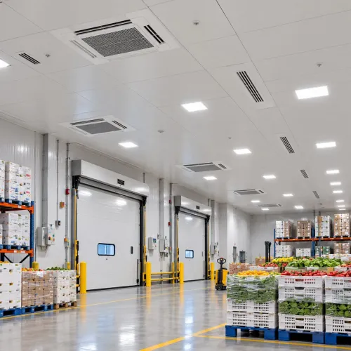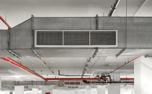
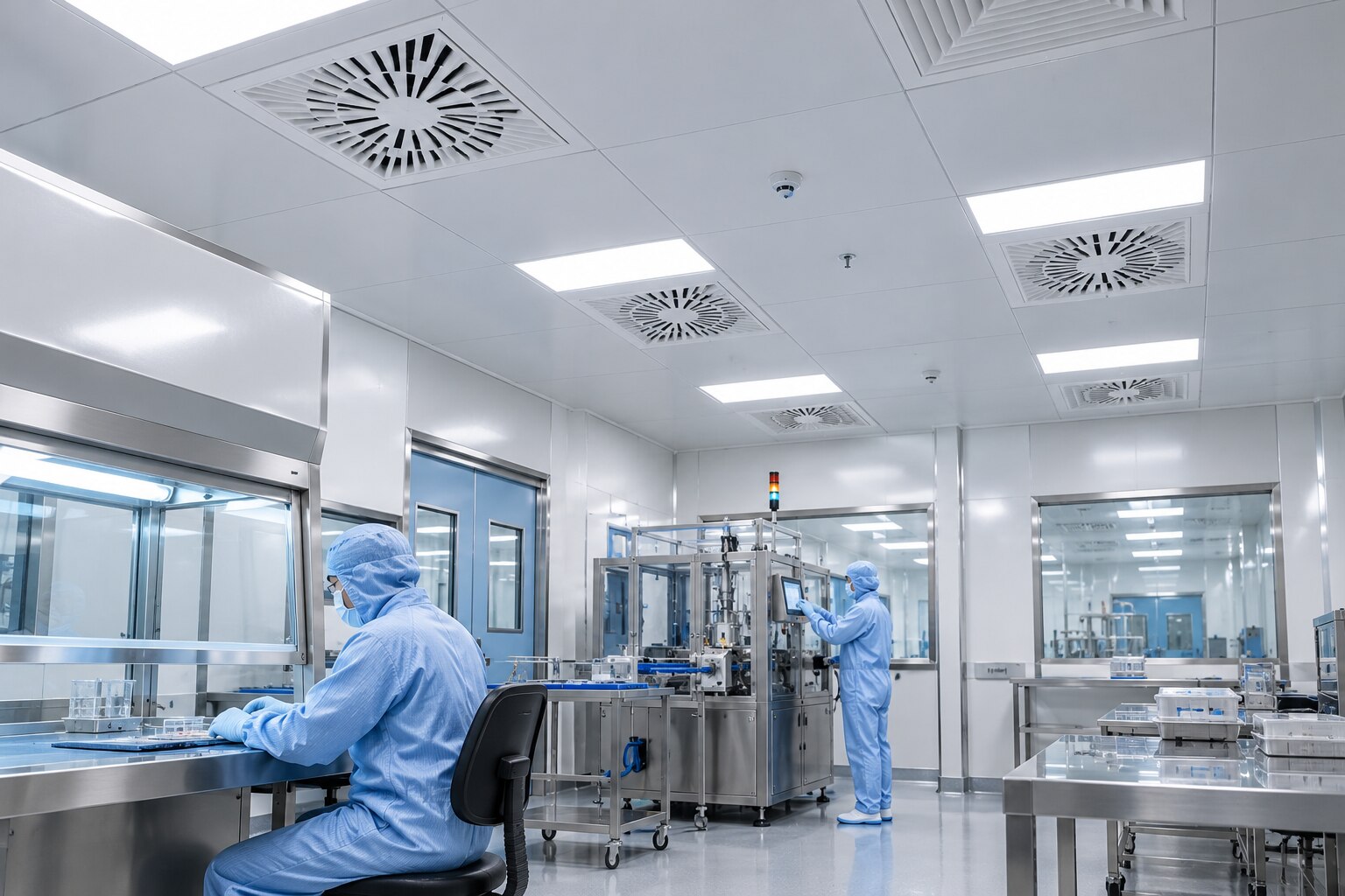
A comfort-HVAC system is designed to make occupants comfortable, not to protect a critical process from particles, vapours, airflow disruption and pressure loss. By the end, you will be able to compare the filtration train, airflow pattern, pressure cascade and verification tests that determine whether a clean room performs as designed.
Key takeaways
- Use staged filtration; HEPA filters do not remove vapours.
- Protect critical zones with directional, low-turbulence airflow.
- Set pressure cascades to control contamination or contain hazards.
- Demand documented airflow tests, pressure readings and particle results.
Why Comfort HVAC Cannot Hold a Clean-Room Condition
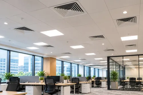
A standard comfort HVAC system fails because it is designed for occupant comfort, not contamination control at a defined work zone. Temperature control versus contamination control involves different design objectives: outdoor-air dilution reduces average pollutant concentration, while recirculation saves energy; neither proves that particles stay away from critical surfaces.
A comfort system misses clean-room control in four ways:
- It distributes air for room-average temperature, creating turbulence, dead zones and entrainment instead of a verified sweep away from critical work.
- Its air-change rate does not establish cleanliness. Required airflow depends on particle-generation rates, occupancy, equipment heat, recovery time, filtration and airflow pattern.
- It may lack terminal HEPA filters, filter differential-pressure monitoring and fan capacity to maintain airflow as loaded filters increase resistance.
- HEPA filters capture particles, not solvents, anesthetic gases, odours or other vapours. Those contaminants require selected gas-phase adsorption or dedicated exhaust.
ISO 14644-1 classifies airborne particle concentration at stated sizes and separates at-rest from operational conditions; it does not certify microbiological cleanliness. A room can pass its ISO particle class and still fail its process.
Reliable control therefore requires verified filtration, airflow patterns, return locations and pressure direction that survive door opening and personnel movement—not merely a thermostat, outdoor-air percentage or nominal ACH target.
How the Filtration Train Captures Particles Without Removing Vapours
A filtration train removes particles in stages, but it does not remove vapours. Each stage has a different job:
- A prefilter catches coarse dust and protects downstream media from rapid loading.
- A fine filter captures smaller particles and extends the service life of the terminal HEPA filter.
- A terminal HEPA filter provides the final particle barrier at the supply point.
Under EN 1822, H13 efficiency at MPPS is at least 99.95%, while H14 efficiency at MPPS is at least 99.995%. MPPS means the most penetrating particle size; a rating quoted at an easier particle size can misrepresent performance.
Track pressure drop and face velocity because rising pressure drop indicates filter loading, while excessive velocity increases leakage risk.
HEPA media remove particles, not chemical vapours or gases. Solvents, anaesthetic gases and odours require gas-phase filtration with a selected adsorbent, source capture or dedicated exhaust system.
A factory certificate does not prove that the installed terminal HEPA protects the room. Confirm protection by checking:
- A continuous gasket seal or gel seal around the filter frame.
- No bypass air around the frame, through damaged media, housing joints or unsealed penetrations.
- In-situ leakage testing with an aerosol challenge and downstream scan across the filter face and perimeter.
- Acceptable pressure drop and face velocity after installation and during operation.
A failed scan means the room is not protected, even when the filter’s EN 1822 rating is correct.
How Supply, Returns and Airflow Patterns Protect the Critical Zone
Air should move from the clean supply surface across the critical zone and toward returns without sweeping contamination back over exposed work. A terminal ceiling supply can create this path, but only when return-air locations, equipment layout and the process position support it.
Choose unidirectional airflow versus mixed airflow from the contamination risk, not from a target air-change rate. Unidirectional flow uses a stable downward or horizontal sweep to carry particles away; mixed airflow dilutes particles throughout the room. The 0.36–0.54 m/s guidance range for unidirectional flow at the working position is not a universal setpoint.
Justify the selected velocity with airflow visualization.
Check the design for these failure points:
- An equipment obstruction creates a wake where particles collect instead of leaving the critical zone.
- People movement disrupts the clean sweep and sheds particles into the process path.
- Poorly placed returns produce reverse flow, dead zones or short-circuiting from supply to return.
- Heat plumes from equipment bend the intended airflow and create local turbulence.
An acceptable room-average particle count does not prove protection at the work point. Airflow visualization, performed at rest and during operation, reveals the actual paths around operators and equipment. Recovery-time testing adds a different check: after a defined particle challenge, it measures how quickly concentration returns to the specified cleanliness level.
Two rooms with the same air-change rate can therefore perform very differently.
How Pressure Cascades Control Contamination and Containment
Set pressure direction from the contamination risk: use a positive pressure cascade to protect a clean process from less-clean rooms, or negative pressure containment for hazardous drugs, infectious agents, and toxic materials. A negative room without dedicated exhaust simply moves the hazard elsewhere.
EU GMP Annex 1 gives 10 Pa as the minimum pressure-differential guidance value between adjacent rooms of different grades when that differential is needed. Treat 10 Pa as a design baseline, not proof of control. Airflow visualization must confirm movement, including during door opening and personnel transfer.
Locate pressure differential measurement points away from supply jets, return grilles, doors and leakage paths. Measure each critical interface, trend the readings, and alarm on both low differential and reversed direction. Poorly located sensors can report a stable cascade while air escapes through a door gap.
Maintain the cascade with coordinated controls:
- Use door interlocks so only one airlock door opens at a time; define recovery time before the next release.
- Provide pressure relief paths sized for closed-door operation and transient door opening, preventing excessive door forces.
- Link exhaust coordination to supply airflow. A sudden exhaust increase can pull a clean room negative; a blocked exhaust can erase negative pressure containment.
- Give pressure-control instrumentation enough range and response speed to handle filter loading, occupancy, airlock sequencing and neighbouring-room operation.
- Test the cascade with doors opened, closed and cycled, then verify the intended direction at every pressure differential measurement point, including doors and leakage paths.
When a process requires both product protection and toxic-material containment, do not choose pressure direction by habit. Model the competing airflow paths and define which boundary takes priority.
Which Standards and Design Tests Turn a Clean Room into a Defensible System
Start with the process risk, not an air-change target. Identify the product, exposed materials, operators, heat sources and microbial control risks, then convert them into limits for temperature, relative humidity, pressure direction, particle concentration and recovery time.
ISO 14644-1 covers airborne particles, not microbial cleanliness, so pair its at-rest classification and operational classification with a separate microbiological-control strategy when the process requires one.
| Framework | What it measures | Design implication |
|---|---|---|
| ISO 14644-1 at-rest classification | Particles with equipment installed but without normal operation | Prove the installed system before personnel and process activity begin |
| ISO 14644-1 operational classification | Particles during specified work | Test with defined equipment, occupancy and operating steps |
| EU GMP Grades A, B, C and D | Particle and contamination-control expectations for regulated manufacture | Set room relationships, monitoring and interventions around the process risk |
Write acceptance criteria before commissioning. Include temperature, relative humidity, pressure differentials, particle-count limits, microbial limits where applicable, filter integrity test results, airflow visualization findings and recovery time after a defined particle challenge. Treat 10 Pa between different EU GMP grades as guidance for the cascade, not proof that doors, operators and transient airflow are controlled.
- Require particle counting at rest and in operation.
- Use airflow visualization to expose reverse flow, dead zones and turbulence around equipment.
- Repeat tests after filter replacement, layout changes or failed results.
- Use specialist engineering support when the room has hazardous containment, unidirectional airflow, difficult heat loads, complex airlocks or regulated release decisions. Arete Consulting Engineers can help translate those risks into drawings, controls and test protocols.
Related products
Clean Rooms/Pharma Clean Rooms are specially designed controlled environments used in the pharmaceutical industry to maintain extremely low levels of particulates,... View product → |
HVAC Solutions HVAC stands for Heating, Ventilation, and Air Conditioning. It refers to the systems used for moving air between indoor and outdoor areas, along with... View product → |
Frequently asked questions
Why can’t a comfort HVAC system maintain a clean-room condition?
Comfort HVAC controls temperature and average pollutant dilution; it does not prove that particles stay away from critical surfaces or work zones.
Does HEPA filtration remove vapours from clean-room air?
No. HEPA filters capture airborne particles, but vapours require a separate control approach, such as adsorption or source control.
How do supply and return locations protect the critical zone?
They establish a deliberate airflow pattern that carries particles away from protected surfaces instead of allowing room mixing to decide where contaminants travel.
What does a pressure cascade control?
A pressure cascade directs air from cleaner spaces toward less-clean spaces, or contains hazardous material by reversing that direction.
Which tests make a clean-room HVAC system defensible?
Documented filtration, airflow, pressure and particle-performance tests provide evidence that the installed system meets its intended clean-room condition.